Sub-Surface Recharge Systems Require Careful Planning
Stormwater management can be a challenging, complex task for developers, especially in urban areas.
Although sub-surface recharge systems promote responsible and sustainable development by returning stormwater runoff to the groundwater after filtering it through underlying soil, implementing these systems in urban settings can be risky. They must be carefully planned and designed to minimize risks and avoid costly disruptions.
Standard design practices for these systems, however, can conflict with the conditions encountered on urban sites. When implementing a recharge system, many risks are unavoidable and often become the developer’s responsibility.
Several cities, such as Washington, D.C., Boston and New York, have implemented retention-first stormwater-management policies that require developers to manage some amount of stormwater onsite. For instance, Washington, D.C., municipal regulations require the retention of a 1.2-inch rainfall event for major land-disturbing activities. The Boston Water and Sewer Commission Stormwater Permit Regulations require the retention and recharge of an inch of runoff from impervious surfaces on nearly all projects and 1.25 inches of runoff for projects greater than 100,000 square feet of floor area. New York City’s Unified Stormwater Rule establishes stormwater-management practices that prioritize retention-first strategies.
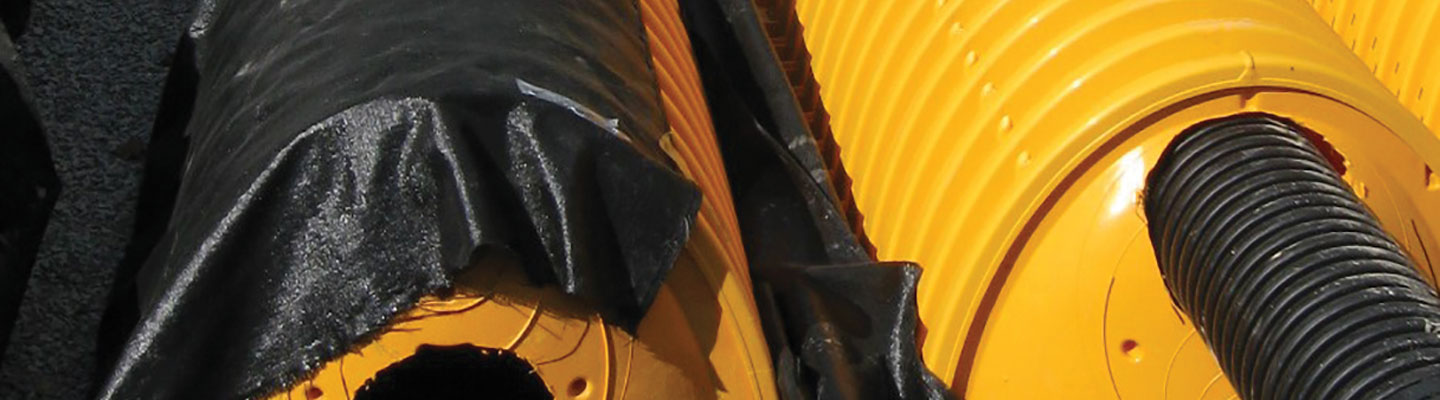
One goal of retention-first stormwater management is to offset the presence of impervious areas. Retention strategies reduce the runoff volume to downstream drainage infrastructure and water bodies by retaining some runoff from impervious areas onsite; recharge systems return this runoff to the groundwater. Sub-surface recharge systems, such as perforated pipe, chambered systems or vertical recharge wells, are often implemented in urban settings.
Conventional External Systems
Placing a sub-surface recharge system outside the building on a project site is not always feasible. In urban settings, buildings often occupy most of the available property. Urban conditions often do not allow for the typical setbacks from structures and vulnerable underground spaces that are needed for sub-surface recharge systems. Seepage flows can introduce hydrostatic pressure on foundation walls and slabs, which can lead to unwanted leakage into below-grade spaces and affect the stability of foundation systems.
There is some uncertainty concerning the recommended setback distances for minimizing disturbances to adjacent structures and properties. For example, the Massachusetts Stormwater Management Standards’ “Rules for Groundwater Recharge” suggest a minimum setback of 10 feet from building foundations and property lines. Detailed site-specific seepage analysis and knowledge of adjacent conditions may reveal that further separation is needed.
Urban settings introduce scenarios where it may not be possible to implement a sub-surface recharge system with the appropriate setbacks and the inherent reliability that comes from using standard design practices. These scenarios force the developer to accept or mitigate the related risks. Mitigation efforts can include structural and waterproofing upgrades to adjacent foundation systems. These are often quite costly.
Available sub-surface space outside buildings in urban settings is often occupied, to some extent, by existing underground utilities. Records for these utilities are often incomplete and can be expensive to validate and supplement with test pits or other sub-surface utility location techniques. The location of the sub-surface recharge system must be separated from each utility; however, the actual positions of these utilities can be uncertain. Additionally, utility owners may not allow the recharge system to raise the groundwater to unacceptable levels near their infrastructure. The discovery of a conflict during construction will significantly disrupt progress and may prevent the installation of the recharge system altogether.
It is not uncommon to encounter fill materials in an urban setting. The highly variable properties of urban fill introduce additional uncertainty for the size and performance of a sub-surface recharge system. Soil permeability directly affects the time required for the system to drain, which is limited by local codes. Because of this, lower-permeability soils result in larger system footprints, complicating the layout challenges for recharge systems in urban areas.
The discovery of groundwater at a shallow depth can further complicate this issue as authorities typically require a minimum separation between the bottom of a recharge system and seasonal high groundwater. Additionally, when considering the effects of the localized increase in groundwater elevation associated with discharge from the system, simplified analyses with conservative input parameters may not yield a workable footprint for the design and require additional investigation and sophisticated analyses.
Developers must also screen project sites for latent environmental issues that may be affected by changing the sub-surface flow characteristics of the site. Due to the discovery of environmental issues or other non-compatible sub-surface conditions, there are situations when developers cannot feasibly implement a sub-surface recharge system. Washington, D.C.’s Municipal Regulation 526 allows a developer to apply for “Relief from Extraordinarily Difficult Site Conditions.” However, the developer must provide acceptable documentation demonstrating the technical infeasibility or potential environmental harm. Without explicit relief provisions, site constraints can lead to negotiations with the approval authority or even stop the approval process altogether.
Internal Systems
Site constraints in urban settings can prevent the installation of a conventional external sub-surface recharge system. Engineers and developers in these circumstances are beginning to consider a sub-surface recharge system within the building as a potential solution. However, this can be a complex and risky proposition.
Internal systems introduce additional challenges relative to the typical external recharge systems. The design team must thoroughly coordinate the proposed internal system with several disciplines, including civil, geotechnical, structural, architectural, mechanical, electrical and plumbing, as elements under the control of any of these disciplines could potentially introduce a conflict with the proposed system. Structural and foundation components, interior utility systems, and the layout and use of the interior space must be considered and arranged to allow for the contemplated sub-surface recharge system and access for maintenance. Given an issue with the system’s performance, removing and replacing an internal system is more involved. It will likely include disruption to the occupied finished space, removal of finishes, structural slabs and other necessary elements.
A vital consideration is how the internal recharge system behaves during extreme events. The design must provide an overflow to prevent flooding into the finished space during severe rain events. Additionally, the design team must consider backflow prevention on the outlet pipes for flood-exposed sites and how the system behaves in flood conditions to prevent the discharge of flows into the finished space. The hydrostatic uplift of the system under flood conditions must also be considered and mitigated.
The effects of seepage flow from an internal system are also important considerations. Sub-surface structural elements can impound seepage flows, introducing potentially unexpected hydrostatic pressure and leakage. Detailed seepage analysis can yield some insight into the preferential path of the sub-surface flows; however, these models are typically based upon available limited information, assumptions and judgments. Because of that, they contain some level of uncertainty and risk. Ultimately, even if these risks are acceptable to a prospective project, the impacts on adjacent properties may be problematic and result in performance problems or disputes.
Putting it All Together
Projects in urban settings will continue to see requirements for the onsite management of stormwater. Retention-first strategies are likely to become more prevalent over time and will continue to introduce complexities and risks to projects. These requirements are manageable, but engineers and developers must be conscious of them and the related risks to integrate recharge systems successfully in their future urban projects.
Sean P. Donlon, Jr., P.E., is a senior project manager with Simpson Gumpertz and Heger; Cory A. Cormier, P.E., is a consulting engineer with Simpson Gumpertz and Heger; and Bryan P. Strohman, P.E., G.E., is an associate principal with Simpson Gumpertz and Heger, which is an engineering firm based in Waltham, Massachusetts.
|
Types of Sub-Surface Recharge Structures for Managing Stormwater The Massachusetts Department of Environmental Protection’s Clean Water Toolkit describes four different types of sub-surface recharge structures that can be used to control runoff. Infiltration pits: These are typically precast concrete or plastic barrels with uniform perforations. The bottom of the pit should be closed with the lowest row of perforations at least 6 inches above the bottom, to serve as a sump. Infiltration pits typically include an observation well. Chambers: These are manufactured modular systems containing open bottoms and sometimes perforations. The chambers are placed on top of a stone bed. Perforated pipes: In this system, pipes containing perforations are placed in a leaching bed, similar to a soil absorption system. Galleys: These are similar to infiltration pits. Some designs consist of perforated concrete rectangular vaults. Others are modular systems usually placed under parking lots. |

RELATED ARTICLES YOU MAY LIKE

From the Editor: As the Economy Improves, What’s Next for CRE?
Fall 2023 Issue

Construction Cost Challenges Shift from Materials to Labor
Fall 2023 Issue